Hound D
Member
- Joined
- Aug 1, 2025
- Messages
- 36
- Reaction score
- 30
Isn't it funny how one modification leads to another, and so on.....Well that's half of the fun right? The story begins like this. A couple weeks ago I had all my components assembled to install my CBI low profile stealth bumber. Before I go any further, many thanks to Trail4r's excellent tutorial on the install found here- CBI Super Stock Covert Bumper Install 6th Gen 4Runner It saved me alot of guessing and grief. The other changes/additions-
Since I had already figured out what my future lighting needs would be, I decided to do things right and set it up nice an clean from the get go. I set out to keep my wiring looking as close to an OEM/professional look, heat shrink, loom and wrap all my conductors, bring all future switch wire into the cab in one penetration through the firewall, and mount up a weatherproof relay box.
I looked around and found this box-IP65 Waterproof Pre-Wired Fuse Relay Box.
A cheap generic tray I could carve up- Auxiliary Power Fuse Block Bracket
And a ton of loom and electrical tape from Harbor Freight

The box has 6 relays, all fused of the load side of the relay, and I needed 5 for my purposes ( 2-dual function light bar, 1 Fogs& bumber lights, 1 Ditch lights, and 1 Roof rack 360 degree lights) with one extra relay for future. The price was steal at $42.
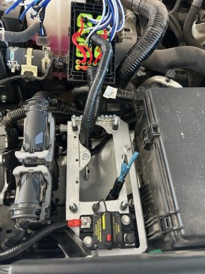
Installing the tray
I took the tray down to size and cut out a square (as much as i could without removing a mounting point) on the bottomot open up the bottom fro the relay box. I'm not installing onboard air, so I utilized the open space on the drivers side between the existing fusbox and the CPU. There are two threaded holes existing and a bolt on the fender side of the engine bay. I used threaded rod and couplers for support struts. I also installed a 30 Amp circuit breaker. I don't plan on running more than lights, so 30 Amps is plenty.


Prepping the Relay Box
The relays are bosch style 5 pin, so the yellow wires are all the normally closed power outputs. I'm not running anything but normally open switching, so I clipped off all those leads as close to the silicone base as possible and sealed them up with some black silicone RTV. I wasn't crazy about the six red common leads on the output side power supply and the six black ground wires on control (switch) side of the relay, so I step spliced both into longer 10 gauge wire with terminals to the breaker and the grounding lug. The long leads give the relay box to allow easy dismount for future wiring.


Next steps in follow up post
- Cali Raised fog light replacements- these really are an upgrade from the stock white TRD Off Road lights
- A pair of Baja Designs S2 Pro Amber Wide-cornering light pods to mount recessed in the bumper-pricey, but Baja designs does make some really great lights
- Rough Country 9500-Lb Pro Series Winch with synthetic rope- A less expensive option, but the bolt pattern on this winch is the same as Smittybilt 10k and fits up nicely. (I don't get a ton of use out of a winch, and I try to save where I can)
Since I had already figured out what my future lighting needs would be, I decided to do things right and set it up nice an clean from the get go. I set out to keep my wiring looking as close to an OEM/professional look, heat shrink, loom and wrap all my conductors, bring all future switch wire into the cab in one penetration through the firewall, and mount up a weatherproof relay box.
I looked around and found this box-IP65 Waterproof Pre-Wired Fuse Relay Box.
A cheap generic tray I could carve up- Auxiliary Power Fuse Block Bracket
And a ton of loom and electrical tape from Harbor Freight
The box has 6 relays, all fused of the load side of the relay, and I needed 5 for my purposes ( 2-dual function light bar, 1 Fogs& bumber lights, 1 Ditch lights, and 1 Roof rack 360 degree lights) with one extra relay for future. The price was steal at $42.
Installing the tray
I took the tray down to size and cut out a square (as much as i could without removing a mounting point) on the bottomot open up the bottom fro the relay box. I'm not installing onboard air, so I utilized the open space on the drivers side between the existing fusbox and the CPU. There are two threaded holes existing and a bolt on the fender side of the engine bay. I used threaded rod and couplers for support struts. I also installed a 30 Amp circuit breaker. I don't plan on running more than lights, so 30 Amps is plenty.
Prepping the Relay Box
The relays are bosch style 5 pin, so the yellow wires are all the normally closed power outputs. I'm not running anything but normally open switching, so I clipped off all those leads as close to the silicone base as possible and sealed them up with some black silicone RTV. I wasn't crazy about the six red common leads on the output side power supply and the six black ground wires on control (switch) side of the relay, so I step spliced both into longer 10 gauge wire with terminals to the breaker and the grounding lug. The long leads give the relay box to allow easy dismount for future wiring.
Next steps in follow up post